LX Forums Forum banner

Paddle Shifter Wiring Harness Install - Step by Step

81K views 77 replies 38 participants last post by  body80  
#1 · (Edited)
Instructions for installing the "jaak hack" Paddle Shifter Wiring Harness, as supplied by plcman.

Included are instructions for the simple adapter board kit, but soon I should be able to add instructions for the lockout and line-lock kits.

UPDATE: Here's the link to my Paddle Install thread, with info on all the steering wheel electrical: Paddle Shifter Install - Paddles and Steering Wheel Connections

And here's a link to Raymond's site from where you can download schematic and instructions: http://www.wlsmithelectronics.com/page2.php


===========================================

Before we get started, the background and acknowledgments:

This wiring kit is used to install a set of paddle shifters onto your steering wheel, which act the same as the auto-stick lever. You have one paddle for upshift and one for downshift. They operate exactly like your shift lever, once the transmission is in Drive.

The combination of these three fellas coming together really made this whole thing do-able.

Anthony (atwong1) found a source for these paddles, when nobody else could find them in quantity, at least not for a good price.

Jim (jaak) discovered the spare contacts in the clockspring, which made it so you no longer needed the receiver/transmitter.

Raymond (plcman) made the harnesses plug-and-play, and incorporated a line-lock option.

===============================================

The quick recap:

Here's the paddle install write-up thread (which was done before the harnesses were available, and back when we thought these paddles were only good as alternatives for the ShiftHammer buttons - at the time you still needed the ShiftHammer transmitter/Receiver combo). It mostly still applies - it's how to install the paddles, not the wiring:
How to install the AMG Shift Paddles on our LX's

Here's where this thing broke WIDE OPEN. Jim (jaak) figured out that there were spare (unused) terminals inside the steering wheel, which allows you to pass two circuits through (one for each shift paddle) - and then wire it directly to the factory wiring harness - no transmitter necessary! All you need is some wire, essentially:
Direct Wired Paddle Shifters

Then Raymond (plcman) said, well, shoot - I'll do you one better - instead of tapping and splicing down there at the shifter mechanism, why not make it plug-and-play? All the connectors the factory uses are commonly available (if you know where to look), so let me rig up some harnesses:
Ultimate--Paddle Jaak Hack wiring kit!
It got even more creative and impressive, but you need to read that one yourself. Most of it's consolidated in the first post.

DaddyGoFast did a great write-up that shows really clearly how to do the connections in the steering wheel, so I skipped that part:
HOW TO W/Pics: Paddle (or in my case button) shifter install -DGF N00b style

Here's the thread about the trouble with the '08 models:
URGENT: Please help atwong1 with ShiftHammer installation

You'll need to have this handy:
How to Remove/Change your Steering Wheel

Here's the current Group Buy for the paddles:
Ultimate Stealth Paddle for ShiftHammer Group Buy Round 3

Also, I want to thank Pete (fnkychkn) for always helping get things right - couldn't do them without Pete's help.

========================================

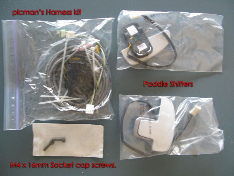
First off, here's what you'll need:

Image


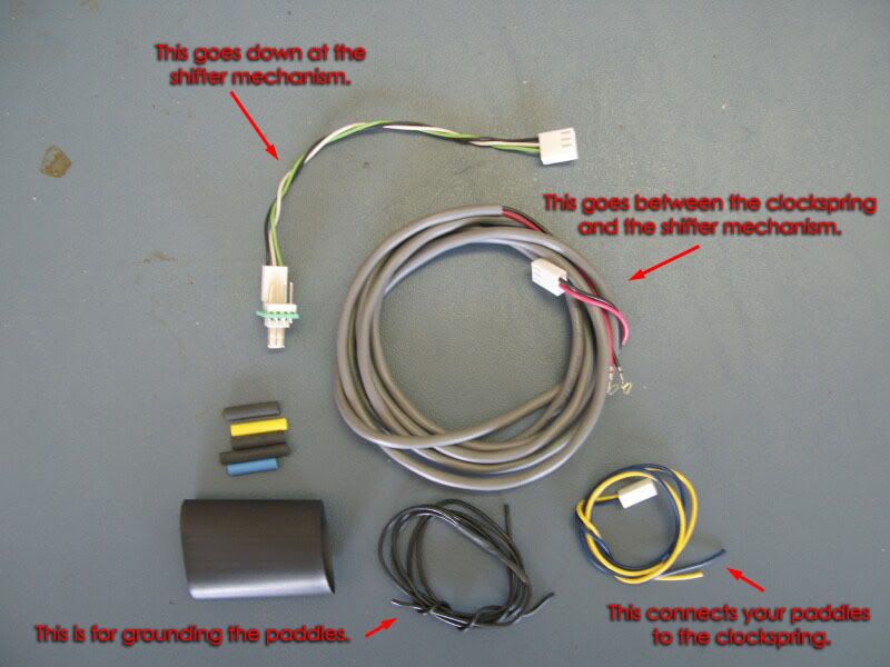
Here's the contents of the Harness kit:
Image


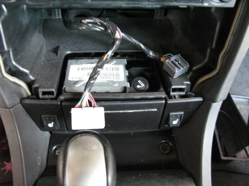
Next Post, Preparation and Disassembly.
 
#2 · (Edited)
Step One - Preparation:

First Thing: Remove the negative strap from the battery (in the trunk). You need to let the airbag capacitors discharge, and you can do some things in the meantime. But before touching anything else, disconnect the battery.

Remove the center bezel, by gently pulling at the outer edges. If you have a Magnum or a Charger, point the top air vents down, and get your fingers in there at that point. Work around the edge, pulling at the points where the spring clips are holding it in. Once it's free, disconnect the wiring connectors behind any switches/components, and move the bezel out of the way.
Image
Image


Once the bezel is out, remove the ashtray by pulling it straight back towards the rear of the car. Disconnect any wiring connectors at the back - cigarette lighter, and/or heated seat switches.
Image


Remove the two screws shown here:
Image


Remove the shift knob by simply unscrewing it counter-clockwise. (EDIT: Not all of them unscrew. I heard something about popping the chrome cap down off the shifter, which lets you access the white plastic fingers that hold it on? Not too sure about that one). Then remove the chrome plastic shift bezel insert, grab the front of the shifter bezel, and gently lift up until it releases from its front clips:
Image


Here you can see how it comes up. Be careful at the back, by the cupholders, as you need to pull it straight up to release it. It may help to use something to gently pry at it from the rear, by the cupholders.
Image


Now empty the armrest console, and remove the plastic tray at the bottom, revealing three hex screws. Remove these with an 8mm socket:
Image


Now remove the two screws shown here:
Image

Once you do so, the entire center console can be lifted out of the way, and set back on the rear seat.

Take a flat blade or panel tool and pull this plastic rivet out of the shifter housing.
Image


Now remove this trim piece in the same manner as most others - it uses two of the same spring clips like you've seen already. Then remove the screw shown.
Image
Image


Also remove one more screw at the bottom, shown here:
Image


Those last two screws hold the lower dash on, but you don't want to remove it quite yet - it'll be in your way. Just set those screws aside for now.

Step Two - Steering Wheel Removal:

If it's been 15 minutes since you disconnected the battery, proceed - otherwise, wait for it.

Take a 10mm socket, and remove the two hex bolts on opposite sides of the steering wheel. These two bolts hold the airbag onto the steering wheel. You'll have to turn the steering wheel 90° to the left to reach the bolt on the left side.
Image


Once they're out, gently pull the airbag towards you, and look at the connections behind it.
Image


The first connection to remove is right on top.
Image


On the top (or backside, as it's installed in the car) of that connector is a ramp latch, indicated by the arrow below. Lift that up to allow you to separate the two parts, as they're shown here already separated.
Image


Now disconnect the two connectors from the back of the airbag. Each has two latch releases, as indicated by the arrows. Squeeze them together and pull the connector out.
Image


Then pull this cable tie straight off the stud it's on.
Image


Now the airbag is free:
Image


Set the airbag aside in a safe place - on a flat surface, face up, somewhere away from any static charge.

Now you need to separate this white connector:
Image


Pull the left half of this connector out from the right, and the steering wheel electrical should look like so:
Image


Now it's time to remove the steering wheel. It's held on by a flathead bolt, which is removed by a 10mm Allen key. This will be the hardest part of the whole process, if you're by yourself. If you have a buddy to hold the steering wheel, it's a breeze. Without a buddy, might I suggest using a cinch strap?
Image


Nah, do yourself a favor and find a partner. You'll need all your body to get that bolt to budge.

Once it's out, the steering wheel is free. Take care when you remove it, to allow the wiring harness to pass through the steering wheel without binding.

Step Three - SCCM Removal:

The Steering Column Control Module (SCCM) contains the clockspring, the SCM, the different switches and controls, etc. - and is removed as one unit. You do not need to disassemble the SCCM any further than shown here.

When the steering wheel is off, this is what you'll see:
Image

(I switched cars again, see?)

First thing, back out one of the T10 screws just far enough so the clockspring cannot rotate, like so:
Image


Next, take some painter's tape and mark the depth of the SCCM shroud in the column, so you'll know whether you reseated it correctly when the time comes. (Note: This will only work if you do not move the steering column adjustments in the meantime. The tilt/depth is what I mean - once the steering wheel is off, leave those alone.)
Image


Now take a T30 screwdriver (not a T30 bit - it might get stuck in there), and loosen the screw that you can't see here. ;)
Image

It will not come out - but you should be able to tell when it has disengaged its threads. That's all you need.

Once it's free, give the SCCM a firm pull straight off the column, and you'll have this:
Image

(Switched cars again - this is my Charger)

Set the SCCM off somewhere safe for now - you won't need to do anything else to it.

Now you'll want to pull the lower dash out of the way. More of the same spring clips at the corners. Then remove the four hex bolts shown here to remove the shield:
Image


You want to be able to get your hand up in there to route the wiring.
Image


Next Post, all the rest.
 
#3 · (Edited)
Step Four - Routing the Harness:

The next thing you're going to work on is the 14-pin connector that connects to the rear of the SCCM. To do so, you need to remove it from its casting. There are at least two ways this connector may be held into the casting, and I'll show you the two that I've seen.

-- First, on an '05 300C SRT:

Image


The 14-pin connector has a little catch on each side of the rear. You won't see these until they're released and the connector is slid out some, but I'll show them to you at that point, so you can see what has to happen to them. The latches need to be pushed towards the driver, but from the rear of the connector. Here you can see the right-hand one:
Image


And with the connector removed, you can see the left one here:
Image


You can also see that I chewed this one up with a flatblade from the front, before I knew how the clips worked. I also broke that left side clip, but it superglued back pretty well.

-- Next, on an '06 Charger:

There's a cable tie at the back of the connector that needs to be cut off first. (sorry, no picture of that - but it holds the wiring bundle to the retainer that you'll see below). Once it's cut off, you simply release the latch on the black retainer, and then slide it down, as you can see in the next two pictures:
Image


Image


And here it is removed:
Image


Once that retainer is off, the 14-pin connector is like the one above, with the clips on the back, and it'll slide out towards the bottom:
Image


-- On All Models:

Now you can slide the 14-pin connector out of its shell, after lifting the edge of the shell over the bump:
Image


Set the shell aside for now.

Now you're going to go ahead and route the main harness from the steering wheel area down to the shifter area. Take the end shown, and feed it in through the steering wheel opening, alongside the wiring for the 14-pin connector.
Image


Reach up and grab it from the lower dash area, and feed it back behind the radio bezel and bring it out down in the bay where the ashtray goes:
Image


Step Five - Connections at the Shifter:

Since you just brought the harness down, let's go ahead and hook it up down here.

Check it out - this is the only connection down here that you need to touch, and look at the colors: Blue, Yellow, Black. Same as the Paddle Shifters, and here's where we add the adapter board.
Image


Release this guy by taking a flatblade to the backside, and pulling it out towards you.
Image


Here he is:
Image


Now you'll need the adapter board:
Image


Plug the factory connector into the adapter board, on the same side as the lead you just put onto the shifter. Black wires go to the same side, as shown:
Image


See how the factory connector goes to the adapter board, and the adapter board's connector goes to the shifter?
Image


Slip the big piece of heatshrink up onto the harness, but out of the way, and then connect the harness to the adapter board (it can only go one way).
Image


Slip the heatshrink back over the adapter board:
Image


And shrink her down:
Image


Now route that harness from here back forward, underneath the carpet and that little plastic rivet you removed earlier. Go ahead and reengage that rivet, and tuck everything up nice.

You can now put the interior back together whenever you want to.

Step Six - Connections at the clockspring:

Looking at the 14-pin connector again:
Image


Here I'm putting the black lead from the harness into position 5 - Note the orientation of the clips in these two pictures:
Image


And here's red going into position 6:
Image


It will help to use tweezers, or hemostats as shown, to get the wires fully engaged into position. You'll hear (and probably feel) it click.
Image


But even so, check out the backside of the contacts to make sure - these look good:
Image


Tape the new harness to the factory harness:
Image


And that's that! All the wiring in the car is done.
 
#4 · (Edited)
Here's a little bit more info on the Linelock/lockout board, to supplement the instructions from plcman.

Image


Image


Image


I still haven't installed a linelock, so it's still not complete, but with what's here, you should be able to install the Harness Kit for functional paddles regardless of which kit you bought. If I ever do install a linelock, I'll add that info here.
 
#10 ·
OK this is going into the KB. Tell me when you think its ready. Two billion beans to you.
Another two billion from me too...

You've done a great job at explaining this. I don't even think about it, I just do it...

If you are good, really good, you can get the connector out of the shifter assembly, without removing the console.

You can also route the wires without removing the metal cover under the column.

And you don't need to release this clip, so I'd remove that from the sequence. That clip helps keep the wires/contacts, in the plastic shell.

Image


It's this one that actually releases the connector....
Image
 
#6 ·
wow this is wayyy to complicated for me. Nice write up junior.
 
#7 ·
Beans to you buddy!!!
 
#8 ·
OUTSDANDING write up. I am affraid of electrical but this write up is for the dummy like me...!
 
#9 ·
Awesome writeup so far!! I have all of the pieces sitting on my workbench but I haven't gotten to the point where I want to tackle this yet. Your post answers all of the questions I had. Thanks Junior. Mucho beans to you! :beerchug:
 
#11 · (Edited)
^^^ OH, gotcha - I'll make that edit up there.

Thanks fellas! I've got a little bit of ironing out to do, and hopefully will add the bit about soldering the steering wheel connections, but in the meantime, DaddyGoFast's will help on that part.
 
#14 ·
OK another 500 million to jaak. I have a steering wheel all wired up and ready to install, thanks to Fast56k, but no solid handhold-the-moron-skeered-to-disable-his-vehicle instructions from there. Now I do. You guys are awesome.
 
#15 ·
Awesome write-up and pics! I was thinking someone should do a complete writeup on this after reading all the different threads and instructions myself and printing them out. Guess someone had to find out about the stuck t-30 bit the hard way! ;)Still working more today on getting that bugger out! Kudos to everyone who made this mod possible!
 
#17 · (Edited)
OK, made some edits to the writeup - mostly nomenclature corrections - I'm now calling it the SCCM, not the clockspring (the clockspring is part of the SCCM), etc.

Also made some edits to the discussion of the 14-pin docking connector.

I'm always open to suggestions and clarifications - I want these things to be right. So if you see something that you think should be addressed, please feel free to PM me about it or post it here.
 
#18 ·
Excellent write up Junior! Not to take any kudos away from Jaak or plcman of course.

For me being a novice at wiring I couldn't attempt installing this without picture instructions. My brain isn't savvy at reading a wiring schematic. This thread will save me lots of time and headaches!!!

A million and 1 beans to you.
 
#19 ·
:blam: Man i did the hard wire install myself last weekend and if I had seen this post first I could have saved 6 hours easy even though i did not have the harness. Great write up just wish i had seen this..... oh well i still got the paddles installed and they turned out great.
Still great write up!:wink:
 
#20 ·
I wish someone made a turn key kit...
 
#22 ·
Great Write up!
 
#23 ·
I've messed with steering wheels and airbags before and have a question. I was making repairs to my airbag in my 97 Cobra when I overtightenedhe clockspring and it snapped. I hadto buy a new airbag module because I didnt unwind it 2 1/2 turns before tightening. Is that so in this case or do you need not worry about it?
 
#24 ·
^^ If I understand your question, the answer is this: As long as you make sure that the clockspring doesn't rotate at any point in the process, and it returns back to its original orientation, you're fine.

You do need to make sure that it does not rotate.

In this picture, you see how to make sure it does not - you back one of the Torx screws out just far enough to prevent the clockspring from turning.

Image
 
#25 ·
^^ If I understand your question, the answer is this: As long as you make sure that the clockspring doesn't rotate at any point in the process, and it returns back to its original orientation, you're fine.

You do need to make sure that it does not rotate.

In this picture, you see how to make sure it does not - you back one of the Torx screws out just far enough to prevent the clockspring from turning.

Image
Yep that was the answer to the question. It was my first attempt to do anything like that. Thanks for the write up and all the information.
 
#26 · (Edited)